Radial
Description
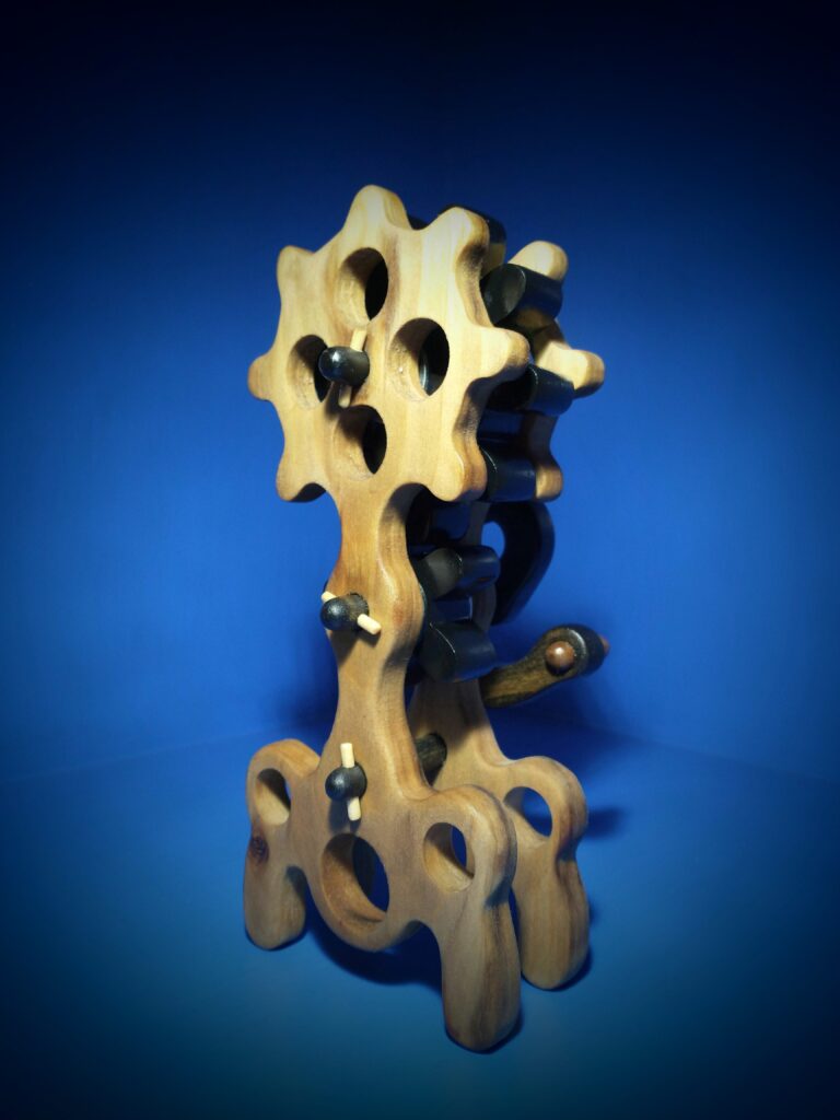
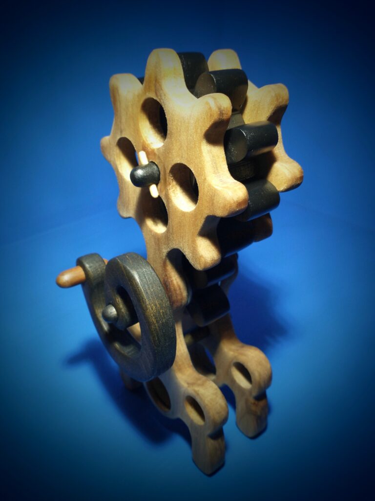
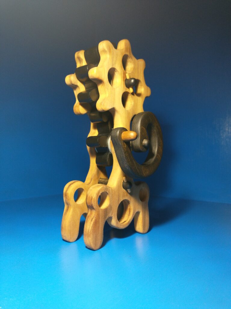
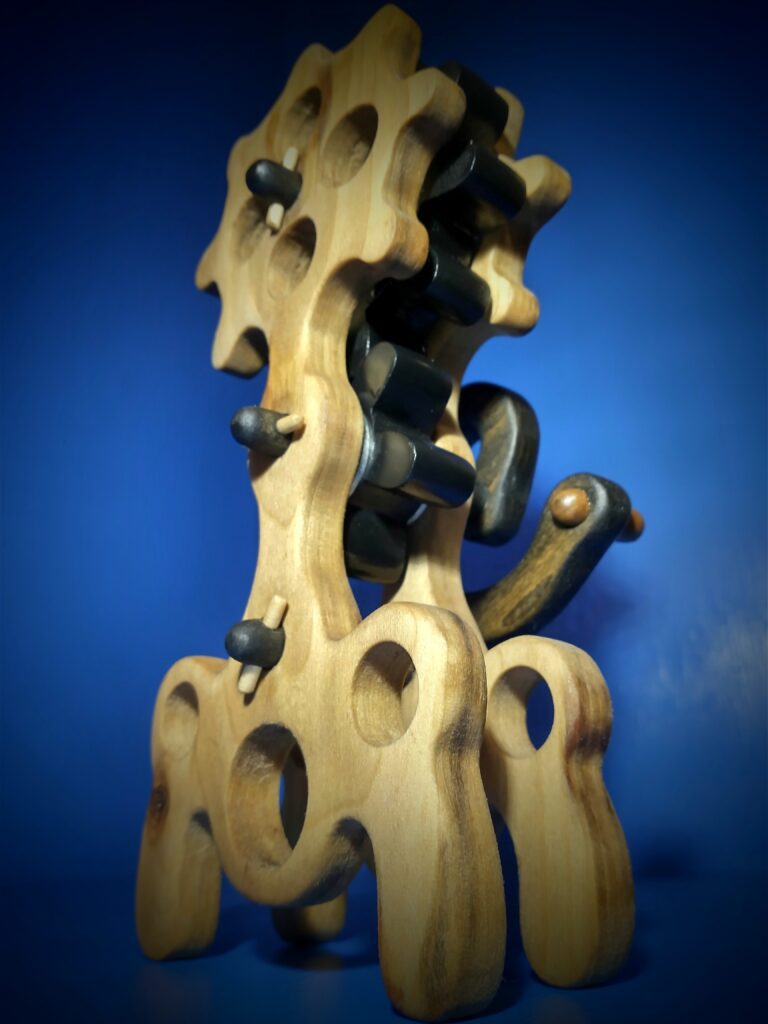
Radial is a term that could be explained as “of or arranged like rays or the radii of a circle, diverging in lines from a common center”. Radial is my fourth prototype for the Automata Project. When designing Radial, I wanted to display a 2:1 ratio of straight tooth gears in the spur arrangement. I designed a straight tooth gear with 10 teeth and a pinion gear with 5 teeth. When designing ratios, you can apply the gear sciences, you can do your designs in CAD, but getting the design to work in wood? That’s the challenge, as anyone who has designed wooden gear ratios has learned. The term “involute profile” and its accuracy clearly comes into effect when designing ratios. Once I was able to get the gears to work, I placed their centers on wood and started to design the base geometry for the prototype. I was leaning towards attempting this sort of ” steam punk” design. I started by drawing a circle on the center of the upper straight tooth gear with 10 teeth. I added the sprockets, and it instantly made me think of the Rolls Royce Radial Engines used in the B52 bombers. I named the prototype at this point thinking of this relationship and the definition of the term Radial. The bottom of the prototype is just a blend of radii, tangents and hole patterns with some legs to create a mechanical, aesthetically pleasing effect.
Radial is a display of one straight tooth gear with 10 teeth and one pinion gear with 5 teeth in the spur arrangement, creating a 2:1 ratio. The gear movement is displayed between two bases created by using radii and tangents and features a hole pattern across its base to give it a mechanical look. The handle is spiral style handle. There were two centers of interest in mind when design the prototype. The first is the front towards the top of the prototype, the sprocket style radial design and on the back side of the project all center of interest is placed on the handle, this was done by making it spiral and rather large in size.